Technical newsletter

EureTechFlash aims to demystify new technologies and make them transparent, to stimulate You as a professional repairer to keep pace with technology.

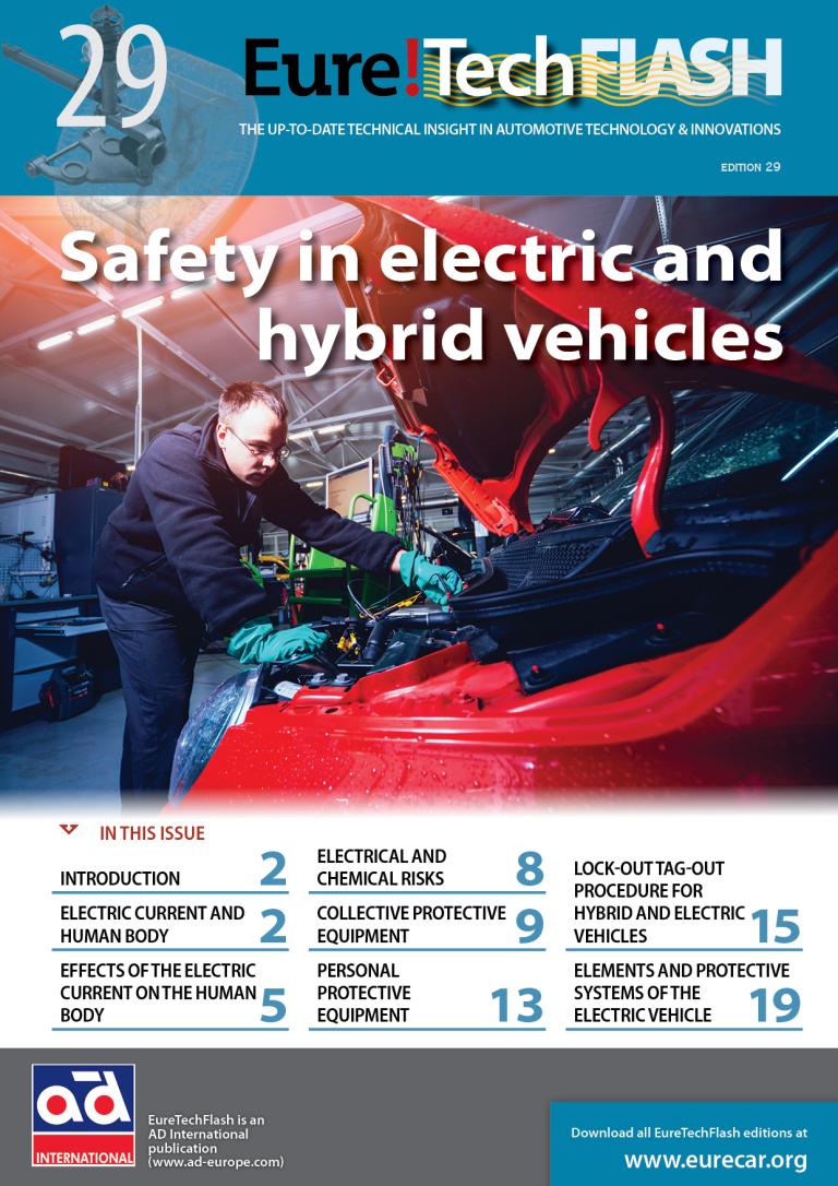
Safety in electric and hybrid vehicles

03.10.2024
The increasing accumulation of CO2 in the Earth’s atmosphere is the cause of the greenhouse effect that, together with the solar radiation, produces the global warming that has been observed in recent decades. Its consequences, such as climate change, are more and more evident, which alters the balance of ecosystems and thus threatens biodiversity and the continuity of life on Earth.
The international agreements that have been adopted to break and reverse this trend require the progressive reduction of CO2 emissions, a great part of which are caused by the use of fossil fuels as energy sources.
This reduction requires the transition towards renewable energies and the increase of the energetic efficiency of consumers to comply with the goals of decarbonisation agreed upon for the different sectors of production. Transport is one of the most relevant sectors due to its direct and almost absolute dependency on oil derivatives.
In recent years, electrification has established itself as the only viable option in the long run to reduce CO2 emissions required by the automotive sector, boosting the development of hybrid-drive or fully electric systems and the electrical energy storage or production that allow their mobility. All these vehicles, including hydrogen cell vehicles, share a common technical feature directly related to the performance and operating range required for their marketing and distribution: they are fitted with a high-voltage electrical system.
Regulation nº 100 of the United Nations Economic Commissions for Europe establishes the certification criteria regarding specific requirements for the electric drive trains to reduce the risks inherent to the high electrical voltage in the scope of normal usage of these vehicles.
According to this regulation, potential differences higher than 60V in direct current and greater than 30V RMS in alternating current are considered high voltage. Nowadays, operating voltages of electrical propulsion systems for passenger cars are between 150 and 800 volts, being 400 V the most common value.
Sales of electrified vehicles are increasing year after year, which is boosting the proportion of these vehicles on the roads and their presence in maintenance and repair workshops. Operations on hybrid and electric vehicles require specific actuation protocols to minimise the risk of electrocution inherent to the existing electrical potential, which may lead to extremely serious work accidents and even death if proper precautions are not taken.
It is obvious that maintenance, diagnostic and repair procedures cannot be considered normal use of the vehicle and, in many cases, require the direct manipulation of the high-voltage system components. However, as of today, there is not any common directive that contemplates the safety precautions needed to perform these operations.
In this legal loophole, manufacturers, standardisation bodies, and government entities have developed their directives. Currently, French standard NFC 18-550 and German standard BGI 8686 are the reference documents for the safety at work on hybrid and electric vehicles at the European level. Their development establishes the criteria for training, accreditation, working competencies, and protocols related to these high-voltage systems on motor vehicles up to 1000 V CA RMS and 1500 V CC.
Electrocution risk is concentrated on the components that work or conduct the high voltage and operations that require intervention in their surroundings. On hybrid vehicles, there is an additional risk derived from the operating temperature of the thermal engine and, on fuel cell vehicles, there are risks related to hydrogen as a chemical element and others derived from its storage at very high pressure.
Download file

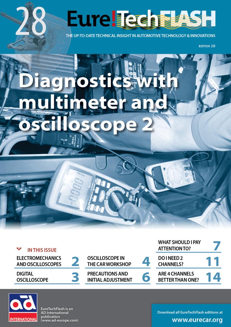
Diagnostics with multimeter and oscilloscope 2

03.10.2024
The measurement of electric current is the method for diagnosing and checking the electrical systems, due to the intrinsic invisibility of both the power and electrical characteristics of the matter.
When the electric current values are invariable, we usually refer to them simply by their name, expressing that the voltage and intensity have a determined value, which is assumed to be constant when the circuit is active.
However, the operation of great part of the automotive electric systems is necessarily variable in order to adapt to the unpredictable driving conditions, climatology or changing safety and comfort requirements, which establishes a variable or even a discontinuous relationship between electrical values and time, called signals. The electric current variation in voltage, frequency, period, intensity, or the combination of the four of them, represents by itself the principle of operation regulation and the principle of data transmission, which allows the electrical systems to adapt to the physical variables related to its function.
The reaction speed, regulation accuracy or increase of transferred data entails the existence of increasingly changing or fast signals. The data interpretation and analysis of their evolution in numerical format is only possible, for the human being, in the past and with obvious speed limits. For centuries, these related data are represented using diagrams to make them easier to understand. Positive quadrant graphs of Cartesian axes (in honour of René Descartes 1596-1650) are the most used ones when time is one of the variables.
The need to represent electrical signals graphically is as old as the discovery of alternating current. Nevertheless, the first tool able to perform this function in real time didn’t appear until 1893, when André Blondel created the mechanical oscillograph.
The development of the first electrical oscilloscope had to wait until 1899 when forming plates and trace sweep were incorporated on the green phosphor screen, derived from the cathode-ray tube invented in 1897. Its usage was delicate and quite limited due to the difficulty to fix the image on screen for irregular pattern signals. This functionality didn’t arrive until 1946, when Howard Vollum and Jack Murdock presented a synchronised sweeping system with an adjustable voltage value, derived from the military technology developed during the Second World War for the sonar equipment of submarines.
First automotive oscilloscopes were developed in the ‘60s and discretely reached workshops in the three following decades, as they were conditioned by their high cost and limited functionality. Their purely analogue operation set aside their usage in the ignition system diagnostics. The operating voltages of 6V and 12V of the remaining electrical equipment of automobiles were insufficient for their representation on screen without an amplification system that, being analogue, would unavoidably alter the nature of the signal, distorting in an unpredictable way their graphical representation as a function of time.
It is true that in that period there was no major need for the diagnostics and repair, being the multimeter sufficient for the measurement of the few variable signals introduced by the newly incorporated systems in cars. After the invention of the silicon transistor, firstly electronics and then informatics would change the world and automobiles, simultaneously creating the need to represent graphically electrical signals of low voltage and high speed. The tool able to do this is the digital oscilloscope.
It is obvious that the expected operation of newly created electronic components and circuit can only be verified by means of a tool able to show with absolute accuracy their electrical “behaviour”. To do so, it must be much faster than the signals that are sought to be evaluated. Clearly this tool created for the check and development is used as a diagnostic tool, therefore, it must be equally valid for repairs.
Download file
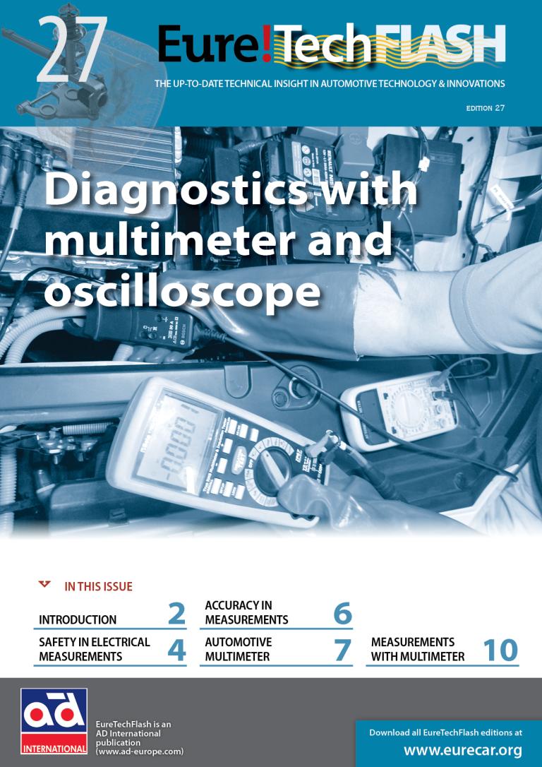
Diagnostics with multimeter and oscilloscope

03.10.2024
From its beginning until present days, the evolution of cars has been unstoppable. If we look back, we can easily differentiate three evolutionary periods related to the automotive electrical equipment.
In the first period, the technical evolution of vehicles focused on the mechanical systems to improve their performance and ease of driving. The car’s electrical system developed and evolved together with the rest of the vehicle in order to satisfy basic needs such as the ignition of the mixture, engine start-up, battery charge or signaling and lighting.
The car electrical installation and number of electrical components increased in a discrete way. However, what is more remarkable is the increase in quality and reliability of the elements rather than their number. The mechanical and electrical systems of the car from that period were clearly independent and, in many cases, their repair as well.
In the second period, the electromechanics itself was born, with the electrification of some engine subsidiary systems or the transmission and introduction of new comfort equipment. The electrical wiring and equipment of cars increased in a significant way to offer new functions or automate some already existing ones. The functional dependence increased in such a way that for the adjustment or the diagnostics and repair of some mechanical systems, the usage of specific equipment for electrical testing and measurement is essential.
The third period started with the introduction of the electronics in cars. The development of memories and processors propitiated in a few years the revolution of the electrical system first and the car as a whole later, to the point of subordinating the operation of great part of the traditional mechanical systems of the vehicle to the control of electronic units that share and process data to manage the operation of electromechanical systems of very diverse nature. In the last two decades, fully electronic systems aimed at entertainment, active safety and driving assistance appeared and multiplied.
Electricity as energy consists in the displacement of particles that are invisible to the human eye. In today’s cars, it is used as activation energy or regulation of the operation of certain components, as a basis for the measurement of many physical parameters and as a means of transmitting information.
It’s evident that purely mechanical systems are decreasing in cars and are less frequently seen in repair works. The transformation of these mechanical systems into electromechanical systems and the introduction of new totally electrical or electronic equipment increase the need of knowledge and equipment for electrical testing in order to carry out successfully the diagnostic and repair operations.
The scope of self-diagnosis that electronic units perform has certain limitations. Its reliability depends directly on the condition of the wiring harnesses, connectors and electrical components that are susceptible to failures, which in many intermittent cases can be located only by means of knowledge and electrical testing.
The 5 senses that allow the human being to perceive reality transmit their “measurements” by means of electrical pulses to brain. However, our capacity to “measure” electricity is practically zero.
Specific tools are required in order to test the electrical systems of cars, being the most important and versatile tools the multimeter and oscilloscope, which allow us to measure and see what is impossible at a glance.
Their characteristics and technical limitations make them more or less suitable for certain works or checks, an aspect that we want to delve into in this article to contribute to efficient operation and accurate diagnosis, which are fundamental factors for the profitability of the workshop.
Download file

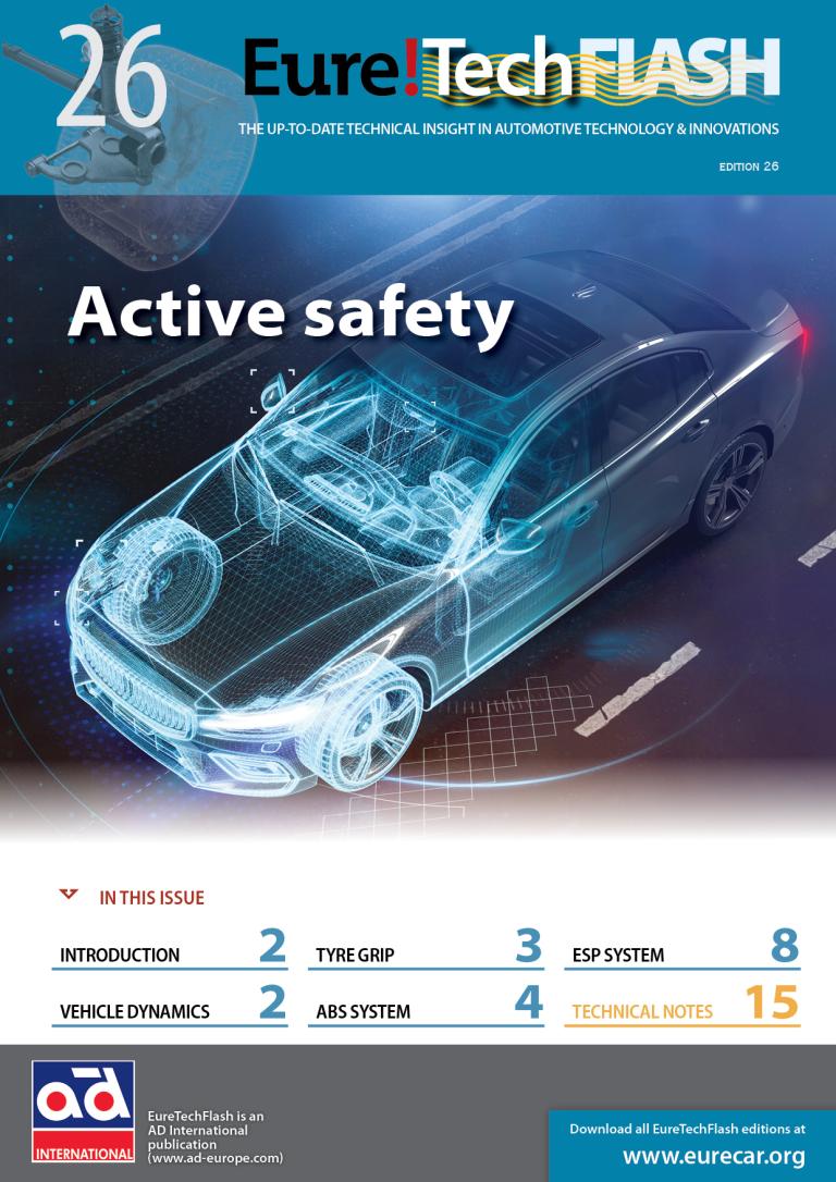
Active safety

03.10.2024
The main cause of traffic accidents at global level derives from the loss of control of the vehicle, normally caused by reacting incorrectly to an emergency situation or exceeding the limit of grip of the tyre. The decisive factors on the frequency and magnitude of such risk situations is the unpredictable environment and road variability, which imply risks for the driver, passengers but also other road users.
In order to reduce the number of critical situations, vehicle manufacturers have developed various technologies of active driving assistance, the so-called active safety systems whose function is to keep the vehicle steering capacity and correct or minimise the consequences of reaction errors. These technologies are based on the electronic control of traditionally mechanical systems in order to avoid the loss of adhesion and path of the vehicle. They rely on the analysis of the physical variables related to the vehicle dynamics and its management by the driver. The electronic systems are provided with logical response and high reaction speed, which in most cases are faster than the capacity of the driver and, therefore, increase the vehicle safety in loss-of-control situations.
The main and most significant active safety systems are related to the brake circuit and allow to maintain the stability and steerabiliity of the vehicle in critical situations and low grip. These are the anti-lock braking systems (ABS) and stability control (ESP). These systems are formed by a high number of components that allow to carry out their functions with total safety, but like any element, they are susceptible to breakdowns and can compromise the safety of the driver.
Download file

Gas analysis in internal combustion engines

03.10.2024
The creation of internal combustion engines and the development of automotive vehicles constitutes a fundamental pillar for the transport of people and goods as we know it today.
Among the variety of engines developed and fuels available, petrol-fuelled 4-stroke combustion engines became dominant historically due to their operating flexibility and ease of control, and are now the most widely used engines in the field of mobility.
A large part of this success is due to the characteristics of the fuel used, which provides a good number of advantageous qualities with just one condition, its proportional mixing with air. As the intake air is a moving gaseous fluid, and the petrol is a liquid that must change state to initiate combustion, the direct measurement of the masses and the calculation of the proportion of the participating substances in each working cycle is, for practical purposes, impossible.
The exact dosing of the fuel mass at the stoichiometric ratio with the air drawn in by the cylinders ensures maximum performance of the engines with the minimum production of polluting substances, and this can be checked from the gases resulting from combustion.
The analysis of the exhaust gases allows the initial mixture ratio and the development of the combustion to be known. This is a powerful diagnostic tool for the resolution of faults and an essential checking process for the control of polluting emissions. The proportion and ratio of the exhaust gases under different operating conditions allow the malfunctioning of the fuel supply system, ignition, timing and other mechanical defects of the engine to be identified.
Download file